LAMINATED-RUBBER BEARINGS: HEAVY DUTY COMPOSITES FOR AEROSPACE AND UNDERSEA
William L. Hinks, Randolph Research Co. (RRC)
This is a transcription from the Powerpoint presentation at the Spring 2013 183rd Technical Meeting.of the Rubber Division of the American Chemical Society.
(Viewing video content requires unblocked access to YouTube)
I'd like to go over some ideas with you about laminated rubber bearings - they’re otherwise known as elastomeric bearings. As you may know, they're a composite of thin elastomer and metal layers.
The basic concept is not new - they've been used for many decades in large pads, with sizes up to several feet or so, to support massive bridge girders, while permitting their thermal expansion. They are now also being used for earthquake protection in multiple units to support entire buildings, while yielding laterally to earthquake ground shaking. Thinness of the layers is a relative term - for those civil engineering uses, the rubber layers may be half an inch thick, but I'm going to concentrate on much smaller dynamic applications. For some years now, elastomeric bearings have done very well in the helicopter industry, and they have potential applications undersea as well. Those applications are what I'm going to talk about.

So let me explain -- what ARE laminated rubber bearings? Here's the idea. They're a stack of many thin metal washers interposed by rubber layers as shown here, and they're all bonded together to form a solid circular mass with an internal aperture. The metal layers or washers are white, and the alternate rubber layers are grey. The layers are greatly exaggerated in thickness for the sake of clarity; in some designs, there may actually be 100 or more rubber layers. In service, this bearing unit would be seated upon a sturdy base or housing. The black arrow signifies a large force acting downward upon the top face
Each rubber layer can shift sideways a small amount. Because of the elastic compliance of the rubber layers, the top can be twisted relative to the bottom; the incremental movements in the rubber layers add up. The illustration shows the movement of a line that's vertical when drawn upon the bearing at rest. The line remains vertical on the metal layers, but shifts within the rubber layers. So angular movement results in a distribution of action between the individual rubber layers.
As the bearing is twisted, an opposing torque builds up, and as you know, rubber in shear provides a wide range of linearity between the shear strain and the shear stress. So, the torque is pretty much proportional to the angle of deflection over that range. It's a torsional spring, and it has little frictional resistance or hysteresis. Obviously, angular motion is limited by the stretch of the rubber in the layers. But the main thing is that they can support an oscillating thrust load between the top and bottom.
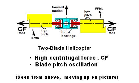
We developed these bearings originally for use on helicopters, and I'd like to explain them further in that context because it shows what they can do. I'll tell you a little more than you may want to know - about helicopters: Everyone is familiar with their rotor blades whirling around at hundreds of revolutions per minute. This figure shows the central section of a two-bladed helicopter rotor, as seen from above and caught in stilled motion. It rotates counter-clockwise, while the whole aircraft flies forward (that is, up on the picture).
Those blades (in yellow) are heavy, and as they rotate about the vertical center shaft, they create a lot of centrifugal force, CF. Even a small helicopter blade may develop a centrifugal force up to 10 tons or so, pulling outward on the central hub. More than that, each blade's pitch angle is oscillated about its own longitudinal axis. It pitches up and down a few degrees, once per revolution of the rotor. For instance, the blade on the right is held at a low pitch angle as rotation moves it forward toward the direction of flight, while a blade on the left is held at a high pitch angle, to catch more air on the "backstroke", as it were.
Each red blade root is held by the central blue hub. The red shaft of each blade passes through the hole in a thrust bearing and pulls on the inboard side of it. Therefore that thrust bearing must support all the centrifugal force, while the pitch angle oscillates up and down a few degrees during each revolution.
That is pretty heavy duty for a thrust bearing. In that environment of high force with small movements, ball or roller bearings tend to fail quickly, due to spalling or "fretting corrosion". Something new was needed.
At that point, our innovation was to replace the rolling element bearings on the basis of a new idea, Laminated Rubber Bearings. They would take the place of the bearings shown in this figure. Their axes would be horizontal as seen here, rather than the vertical axis in the first figure.
***************************************************
Here is what these composites of rubber and metal can do: They can handle many tons of centrifugal force while permitting small pitch angle oscillations of each blade, hundreds of times per minute. And lifetime is increased over ball or roller bearings without any lubrication. A natural rubber compound is generally used because of its high resilience and low hysteresis dynamic properties, resulting in low heat build-up.
This is a technology that’s now common in the helicopter industry. Laminated rubber bearings (usually called "elastomeric bearings" in the industry) are now made by a number of companies, including the Lord Corporation and Chicago Rawhide, and are used on many or most helicopter designs.
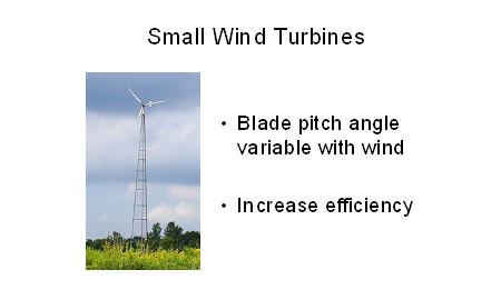
We also see a potential market for a similar application on the rotor blades of small wind turbines. If they can change blade pitch in response to changes in wind speed, that can mean better overall efficiency.
Now, those high forces I spoke about may squeeze a laminate bearing with pressures up to 10,000 psi, but the actual compression is very slight - some small two-inch diameter bearings we make compress less than 0.010” or so under load. They don't compress because the rubber layers are often thinner than a sheet of paper, i.e., .002"; so thin that they can't extrude out from between the metal layers. In some laminate bearings, most of the compression, slight as it is, is actually due to a decrease in volume of the rubber. So it turns out that these elastomeric bearings are RIGID against normal force, while still very elastic laterally.
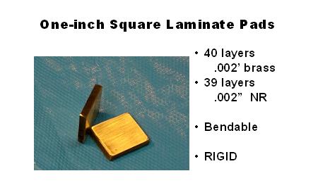
Here are two 1-inch laminate pads, about 3/16” thick. Each of them has 40 layers of brass and 39 layers of NR. As a demonstration, I'm going to clamp them in a big vise. I'll sandwich a metal bar between them and clamp down on the assembly with a couple thousand pounds.
The bar oscillates easily back and forth after tweaking it by hand. But front-to-back of the vise, the bar feels as solid as if the laminate pads were not there. The rubber does not squeeze out from between the metal layers.
So I want to amplify somewhat on what may appear to be contradictory, i.e., that really high pressure, but no extrusion of the rubber layers:
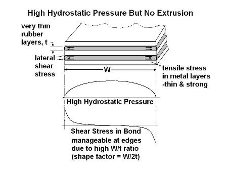
Let's look internally at the hydrostatic pressure within a typical rubber layer. This is a simplified case, the cross-section of a few layers taken out of very long (semi-infinite) laminate strip with width W. The thin grey rubber layers are interleaved with metal layers and it is loaded evenly over its length and width. This is similar to a cross-section across one side of the thrust bearing we saw before.
The plot of internal hydrostatic pressure shows it to be higher than average between the edges of the strip, but it drops to zero at the edges. Again, that average may typically be 10,000 psi. The pressure causes outward or lateral shear stress at the rubber-metal bonds. Some sideways arrows in the rubber near the edges indicate that shear stress. It anchors the rubber layer.
At the bottom, that lateral shear stress is plotted. It will be zero at the middle of the strip and maximum at the edges. That is, the large transition from internal pressure to atmospheric pressure at the edges of the rubber layers will result in the most lateral shear stress in the bonds there.
But that shear stress is very much limited by the thinness of those rubber layers, labeled by tr. Even though the hydrostatic pressure in a rubber layer is high, it acts toward the edges upon a very thin cross-section (e.g., .002" thick). That high pressure times a very small area results in a relatively small and manageable shear stress upon the rubber-metal bond. This thinness of the rubber layers relative to their extent in width is what makes the thing resistant to squeezing-out of the rubber; i.e., the width-thickness ratio is high. In other words, the shape factor is high.
The term “Shape Factor”, as seen in rubber engineering literature, is defined as the loaded area divided by the unloaded area, and is 1/2 the width-thickness ratio in this simple case; i.e., SF = w / (2*tr). We frequently use a w / t ratio > 200:1, i.e., SF > 100..
As a consequence of the internal pressure, the metal strips in a laminate stack are pulled-upon outwards as they restrain the rubber through the bonds. So there is tensile stress in the metal layers, and they must be strong, with an adequate factor of safety. Suppose the metal layers are the same thickness as the rubber layers, as shown. Then the maximum tensile stress in the middle of the strip will be the same as the average hydrostatic pressure in the rubber in this simple case, typically 10,000 psi.
To minimize the stack height of the bearing, it is desirable for the metal layers to be as thin as possible. So there is an advantage in using thin metal layers with high tensile strength.
We at RRC started with and have specialized in laminated bearings with very thin laminates and as many as 100 layers for relatively small helicopters. Most manufacturers for large helicopters have necessarily gone to thicker, fewer layers.
In our case, we tend not to use an adhesive to bond the rubber and metal layers together. An adhesive would add thickness comparable to the thickness of the rubber layers themselves (a few thousandths of an inch). So we usually avoid adhesives by making use of the natural chemical bond of NR to some alloys of brass. We frequently use a high-tensile cartridge brass.
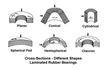
So far we’ve talked about only the simplest type of laminated rubber bearings. They all had flat metal and rubber layers and operated as thrust bearings. But as well as those planar thrust bearings, this figure shows cross-sections of some other possible shapes. The layers may have a conical shape (as in a lampshade), or hemispherical shapes, or may be wrapped into a cylinder like a bushing.
Planar bearings handle thrust loads, and those loads are indicated by the heavy downward arrow representing axial loading. Planar bearings permit angular oscillation in the helicopter application, but they can also allow lateral shifting. Those motions are both noted by the small arrows drawn on its top surface. If you shifted the top of the bearing to the left you would get an incremental movement of the layers shown by the slanted dashed line at the edges of the figure. Planar bearings are the easiest to make – they don’t require any forming of the metal layers.
The bearing on the right has chevron-shaped layers, and it can support thrust loads with angular oscillation as does the planar bearing, but the shape of its layers precludes lateral shifting. That property tends to permit a taller bearing for the same load without any need for external lateral support.
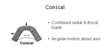
The conical configuration can handle a combination of thrust and radial loads as seen by the side and top heavy arrows. It also allows angular motion about its longitudinal axis.
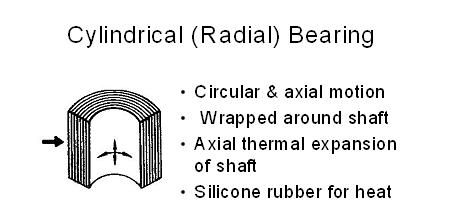
The cylindrical bearing is meant for radial loads like a bushing, as seen by the heavy side arrow, but it has much greater load capability with its multiple layers. It can permit angular rotation, but also small axial shifting motions as seen by the longitudinal arrow inside. One application of this cylindrical configuration, with the layers wrapped around a shaft, was to rigidly support that shaft while allowing for its axial movement due to thermal expansion in a hot environment. Silicone rubber layers were used in that case to cope with the higher temperatures
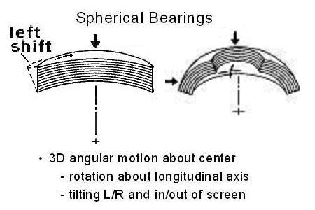
Two spherical bearings are seen here. Each of their rubber and metal layers is a segment of a sphere, where each layer has the same center point. That makes it possible for their rubber layers to be shifted sideways, in any direction, tangential to their common center point. Of course, they can still rotate angularly about their longitudinal axis.
The pad-like spherical bearing at the left can sustain thrust loads while permitting a lateral shift, shown at its left side by dashed lines. This type has been used to support a self-leveling loading fixture, for instance.
The hemispherical bearing on the right can support a thru-shaft with thrust and radial loads. That permits angular motion of the shaft about its longitudinal axis, as in the planar thrust bearing. But the shaft can also tilt left or right and in or out of the screen, or any 3-dimensional combination, as shown by the small arrows.
Many of the large helicopters use spherical elastomeric bearings. They carry the regular thrust load and do the ordinary oscillation about their pitch axis, but the spherical shape permits them to also accommodate small dynamic angular movements of the blades about their other 2 degrees of freedom; namely, lead-lag and flapping of the blades as they rotate.
So a laminated rubber bearing can resist thrust, or radial, or combined forces, depending upon the configuration of its laminate surfaces, while providing up to 3 degrees of freedom.
So what goes into design? Some of the design factors that can be dealt with for various end results are the diametral dimensions and height, load forces, torsional stiffness, fatigue life, angular range and maximum torsional shear strain. Here, I'm talking about oscillating TORSIONAL shear strain, as caused by twisting the bearing, as opposed to OUTWARD shear stress or strain as caused by internal pressure in the plots we saw.
Here are some of the numerous relationships between these factors. For instance, torsional stiffness is proportional to the 4th power of diameter, but inversely proportional to the total height of the laminate stack. Torsional shear strain for a given angle of rotation is proportional to diameter and inversely proportional to height. Fatigue life is dependent upon maximum oscillatory torsional shear strain, internal pressure and other factors.

Well, that covers the helicopter application. More recently, Randolph Research has developed what we call Bearing-Seals. These provide interesting new opportunities for the design of undersea craft, and I'll go over the idea with you.

Bearing-Seals are simple: They are in fact the very same laminated rubber bearings I've already described. It turns out that these devices can function as hermetic seals after the top and bottom are enclosed and sealed. The bearing stack has a central hole, and obviously, there's a circular body of solid rubber and metal between the interior hole and the exterior of the bearing. It's a barrier all around - seawater can't move from the outside to the inside, or vice-versa.
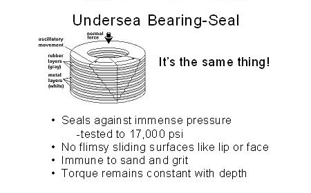
This barrier prevents the flow of liquids or gasses between the periphery and the aperture even under very high differential pressure. Unlike ordinary lip or face seals, they have no flimsy sliding surfaces, so they are immune to scarring by sand. Further unlike lip and face seals, the torque vs. deflection curve is unaffected by pressure at depth. Altogether, they can reliably handle very high external hydrostatic water pressure as well as providing a sealing function.
So what can we do with a bearing-seal?
Suppose we have a pressure vessel - like a submarine.
And suppose we want to have a sealed shaft that extends from the inside of the hull to the outside - like a diving plane shaft.
We can do that with a bearing-seal.
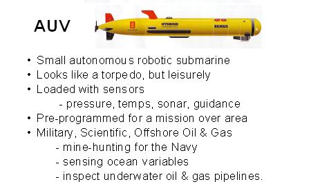
I'll give you an example - on a smaller scale than a huge submarine! A bearing-seal as it might be used in a so-called Autonomous Underwater Vehicle, that is, an AUV. An AUV is a small torpedo-shaped robotic submarine, but it’s really pretty leisurely in speed. It's loaded with sensors to detect its environment underwater and it's pre-programmed to carry out some underwater mission, such as mine-hunting for the Navy, or sensing ocean variables, or inspecting underwater oil and gas pipelines. Many organizations have developed AUV's for military, scientific, and commercial purposes.
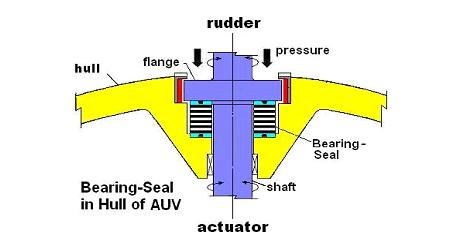
This cross-section represents the top of an AUV's circular pressure hull. The hull is yellow in color, and the down-curving edges are part of the hull's complete circle. The yellow inward bulge at the center encloses a cylindrical cavity or receptacle. A dark blue flanged shaft passes through a bearing-seal within the receptacle. The bearing-seal has white metal and black rubber layers and light blue top and bottom end plates. The end plates are sealed by O-rings - black spots - relative to the shaft flange and the bottom of the receptacle.
The large arrows at the top represent intense hydrostatic pressure, pushing down on the shaft and its flange, and therefore upon the bearing-seal. Seawater also presses into the gap around the sides of the flange and surrounds the bearing-seal. But seawater can't get past the bearing-seal and therefore not into the vessel.
And, of course, the shaft can be rotated through an angular range due to the elasticity of the bearing. The shaft is centered by two radial bearings. One (or maybe both) is a radial bearing in the air environment below the bearing-seal. The other is shown above the bearing-seal, in seawater. A Teflon bushing that's red in color supports the shaft on its flange.
Now, as indicated, the shaft could be used to turn an outside rudder by an actuating mechanism inside of the hull, in the air environment.
So the bearing-seal both mounts and seals the external hydrofoil, while withstanding the pressurized seawater around it. Such an external hydrofoil could then control not only the direction of an AUV underwater, with a rudder, but also its climb and descent, using similar bearing-seal configurations with horizontal axes to control diving planes.
What might be considered rather far out would be to employ it for a fishtail mode of propulsion rather than using a propeller, by swivelling a tail fin back and forth. It's been suggested that mimicking the natural motions of fish could provide superior maneuverability, efficiency and stealth of underwater propulsion, and a number of organizations have been looking into it.
Generally speaking, potential applications of bearing-seals can be found where it's advantageous to do control and actuation in an air environment. It becomes possible to use non-esoteric, low cost, off-shelf electric actuators, without concern about their corrosion in seawater. We have used a specially-developed NR compound to deal with the saltwater environment.
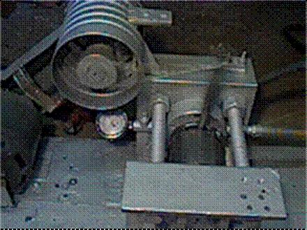
Here's an example of tests we've run on small bearing-seals. At the lower right center of the picture is a hydraulic press, and the shiny dark cylindrical pressure chamber that is centered in it. The hydraulic press forces a piston into the cylinder of the pressure chamber, and that pressurizes the seawater and the bearing-seal inside. A flanged and sealed shaft passes through the internal bearing-seal and extends out into the air. A vertical lever arm is attached to the end of the shaft, so it can be oscillated back and forth by a connecting rod and crankshaft.
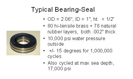
This is one type of thrust bearing-seal that was tested. It has an outside diameter a little over 2 inches, an ID of 1 inch, and about 1/2 inch height, or thickness. It has steel center plate (for lateral support if needed) and end plates. It has 80 laminations of high-tensile cartridge brass, with a total of 78 intervening NR layers. Both the rubber and brass layers are only .002" thick. This bearing-seal was placed into the tester under 10,000 psi pressure, and the oscillator ran at an accelerated speed of about 600 cycles per minute at +/-15 degrees, for over a million cycles without failure. The lever arm could also be easily moved by hand through the same angle. Some tests on that unit later went up to the crushing pressure of 17,000 psi - maximum sea depth - under continuous oscillation for many more hours.
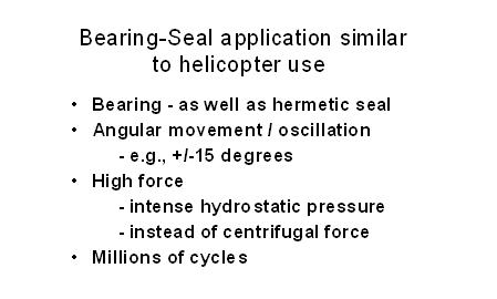
So what a bearing-seal has in common with the helicopter application, then, is high force capability with limited angular oscillatory movement, as well as the capacity for long life.
We are continuing development of laminated rubber bearings for dynamic control purposes, particularly the conical and spherical configurations. Although some applications have yet to be proven, these examples are meant to suggest some of the opportunities that can be opened up by this new approach to design.