LAMIFLEX® BEARINGS FOR HELICOPTER BLADE RETENTION
 CONVENTIONAL BLADE RETENTION
This is a simplified top view of a helicopter rotor hub with two attached rotor blades.
Large thrust loads (typically 15,000 pounds or more) due to centrifugal forces act upon the blades
as the rotor revolves at several hundred RPM (500 RPM or more for small helicopters). The blade root shafts
must be movable through a small angle about their longitudinal pitch or feathering axes relative to the rotor hub
to control the helicopter. This angular motion is generally made up of two components: an average angle
controlled by the pilot's collective pitch stick; and a superimposed sinusoidal oscillation of several degrees
at a frequency of one cycle per revolution of the rotor blades about the vertical axis. That is, as each blade rotates,
its pitch angle is varied to follow the tilt of a non-rotating swash plate, that tilt being controlled by the pilot through
the cyclic pitch stick. The total stop-to-stop feathering angular motion of the blade may be about 20 degrees.
Rolling element bearings (angular contact or roller types) have been conventionally used in the rotor hub
to retain each blade because a low coefficient of friction is needed under the large thrust load to permit muscle-power
control of the feathering angle. However, there have been several problems with these bearings. First, early failure
has often occured due to fretting corrosion. That is, the concentrated high surface stresses caused by heavy loading
together with repeated small cyclic pitch movements about a spot result in metal fatigue and pitting of the rolling
elements and races. In the attempt to avoid this, several bearings may be stacked together to share the load.
High tolerance bearings are required and their replacement is costly. Frequent lubrication is the rule, and adds to maintenance costs.
Another problem: even with the relatively low coefficient of friction of rolling bearings, the centrifugal thrust load is
so high that friction torque is substantial, abruptly reversing when the direction of feathering motion of the blades is
reversed twice per revolution of the rotor. This results in reactive vibratory forces reflecting back upon the cyclic pitch stick,
and becoming a source of annoyance and fatigue to the pilot.
THE LAMIFLEX BEARING
The Lamiflex bearing was developed by Randolph Research (RRC) to deal with this kind of situation: very high compressive
loads and limited angles of motion, with small size, reasonable cost and no lubrication. Having little noticeable friction, they instead develop a light-to-the-hand torque proportional to the angle of motion despite the high load. It is possible in some cases to tune the system so that stick feedback forces are nearly eliminated-- more later.

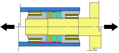
These characteristics are the result of an elastomer-metal composite construction. Lamiflex bearings comprise a circular stack
of thin metal laminations or layers normal to the load, separated and bonded together by thin layers of rubber as seen in the
section above of a hub expanded from the overall view of the rotor. The thicknesses of the metal and rubber layers (blue and
yellow respectively) are greatly exaggerated for clarity; they are each typically only about .002" thick, and there may be several
hundred layers. The Lamiflex bearing surrounds a shaft (light yellow) and its blue load faces are flanked by and compressed
by gray-colored flanges that are threaded to the shaft on the left and the inside of the shell of the hub on the right.The large
arrows represent the tons of centrifugal force pulling upon the shaft and passed through the Lamiflex bearing to the hub.
It can also be seen that limited angular oscillation of the helicopter shaft is possible through the accumulated shearing
movements of all of the rubber layers.
The rubber layers are so thin compared to their width that their outward shear stress tending to result in extrusion out from
between the metal layers is small. Since the rubber can't be extruded and has a very high resistance to compression in volume,
the axial deflection of the bearing under load is small, .010" being typical. And since the Lamiflex bearing absorbs loads over its
entire face area rather than in the very small total contact area of a rolling element bearing, stresses are much smaller, and
sharing the load over several bearings is unnecessary.
As an example, the RRC type T1-A Lamiflex bearing design
has inner and outer laminate diameters of 1-5/8" and 2-1/4" diameter, respectively. This gives a laminate area of about 2 square
inches, so that with a design load of 20,000 pounds, it has 10,000 psi compression stress in the rubber and about the same tensile
stress in the cartridge brass metal layers that are rated for 100,000 psi. The T1-A was the first laminate bearing designed for
helicopter use, specifically for tests run by the armed services at Wright-Patterson Air Force Base
.
When a large load is impressed on a laminate bearing as tall axially as shown in relation to its cross-section, it may have a tendency
to bow-out laterally due to shifting in the individual rubber layers. To prevent this, some means of lateral support of the mid-layers may
be necessary, and so in the illustration, the bearing is assembled from separate sections of laminate, two in this case. Each section
is so short (although containing many layers) that the bowing effect within each is prevented. They are separated by and bonded to a
flat metal washer with a polished OD. This "slipper ring" transfers any resulting small sideward forces from the laminate sections to
the encircling sleeve, lined with a reinforced TFE bearing material, while allowing relative angular movement as the end of the bearing
oscillates. The lateral force upon and drag of these TFE surfaces is negligible and their wear is insignificant over hundreds of hours
of use. Whether separate sections are required or not depends upon the load, OD, ID and total rubber height required. Other means
of lateral support are possible, including the use of layers that are self-supporting conical or chevron shapes; these are generally more expensive.
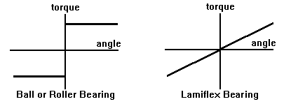
The maximum total angular motion possible in the bearing may be typically 150 degrees, 5-7 times what is actually used. The torque
of the bearing is essentially proportional to the rotation angle and is little-affected by the load; ie, it is a torsional spring with torque about 70 in-lb.
at 10 degrees for the T1-A. With negligible friction, there is no abrupt reversal of stick feedback force with reversal of blade pitch rotation, as happens
with rolling element bearings, illustrated below.
 In fact, most of the energy put into "winding up the bearing" is returned when the angular rotation is reversed. The oscillatory spring-mass
system formed together with the feathering mass moment of inertia of the blade has been used to advantage in some laminate-bearing-equipped
helicopters. The idea is to "tune" the blade into resonance about its feathering axis at the frequency of its rotor RPM so that it "wants" to continue
oscillating. The idea is attributable to Alb Ballauer of Enstrom, and was first applied on the bearings that RRC designed for that helicopter.
This approach may effectively eliminate cyclic pitch feedback problems without need for any hydraulic boost.
It is often advantageous for the Lamiflex bearing end plates to be tabbed or keyed to their mating members for maintenance of a desired
neutral blade pitch relative to the hub.
SERVICE LIFE
Lamiflex bearings have been proven to have good service life. As a new idea for helicopters, extensive tests of the T1-A bearing were run at
Wright-Patterson Air Force Base, loaded to 20,000 pounds and oscillated at +/- 5 degrees at 300 CPM. After 1065 hours of perfect operation,
the angle was increased to +/- 7.5 degrees and run until a total of 1377 hours (almost 25 million cycles) was accumulated with essentially no degredation.
Accelerated tests have been done by RRC on T1-A and other types of Lamiflex bearings for over 100 million cycles under similar conditions.
Generally, it has been found that they obey a fatigue stress (or strain) law similar to that of other materials; the lower the oscillating shear stress,
the longer the lifetime cycles. Fatigue failures that have occurred in test under conditions of excessive strain are gradual, without collapse under
load. In practice, torque has been found to generally increase somewhat after hundreds of hours of cycles or years of use, giving warning that
extends over a period of time while function is maintained.
The result is a type of bearing with long life, needing no routine maintenance. It is light in weight and small, with reasonable cost. Following
the military tests of the T1-A, rubber-laminated bearings have since become an industry standard solution for all sizes of helicopters.
RANDOLPH RESEARCH COMPANY
Randolph Research Company, the inventors of the Lamiflex Bearing and recently patented
Bearing-Seal concepts, design and manufacture these unique units in various custom configurations.
WL Hinks
E-mail: whinks@randolphresearch.com
Phone: 330-760-0744.
Updated 10/20/2011
Home Page


